Setpoint DIY Kit — Build Guide (Module Carrier)
For the module-based carrier board: an ESP32-C3 SuperMini, a TP4056 charging module (with protection), a slide switch, and a DS18B20 probe, soldered onto the carrier. All through-hole / module soldering — no fine-pitch SMD. Budget ~30 min.
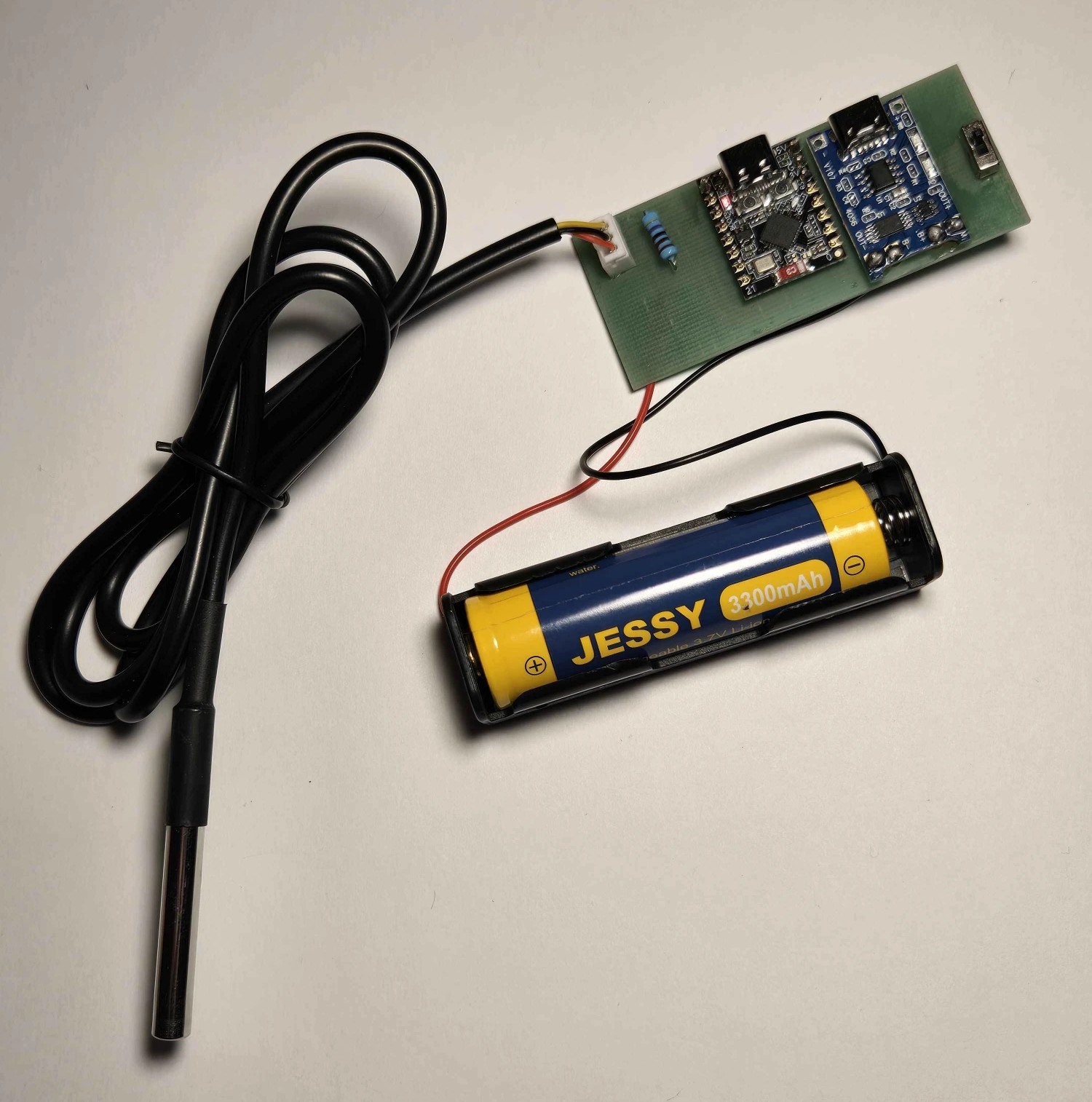
What's in your kit
| Part | Notes |
|---|---|
| Carrier PCB | The through-hole board |
| ESP32-C3 SuperMini | The brain; has its own USB-C (for flashing) |
| TP4056 module (with protection) | Charges the cell over its own USB-C; DW01+FS8205 protection on-board |
| SPDT slide switch | Power on/off (stops shelf drain) |
| DS18B20 waterproof probe | Temperature sensor |
| 4.7 kΩ resistor | DS18B20 pull-up (+ any others per silk) |
| Header pins | To mount the SuperMini + TP4056 module |
| 18650 holder (optional) | For the cell |
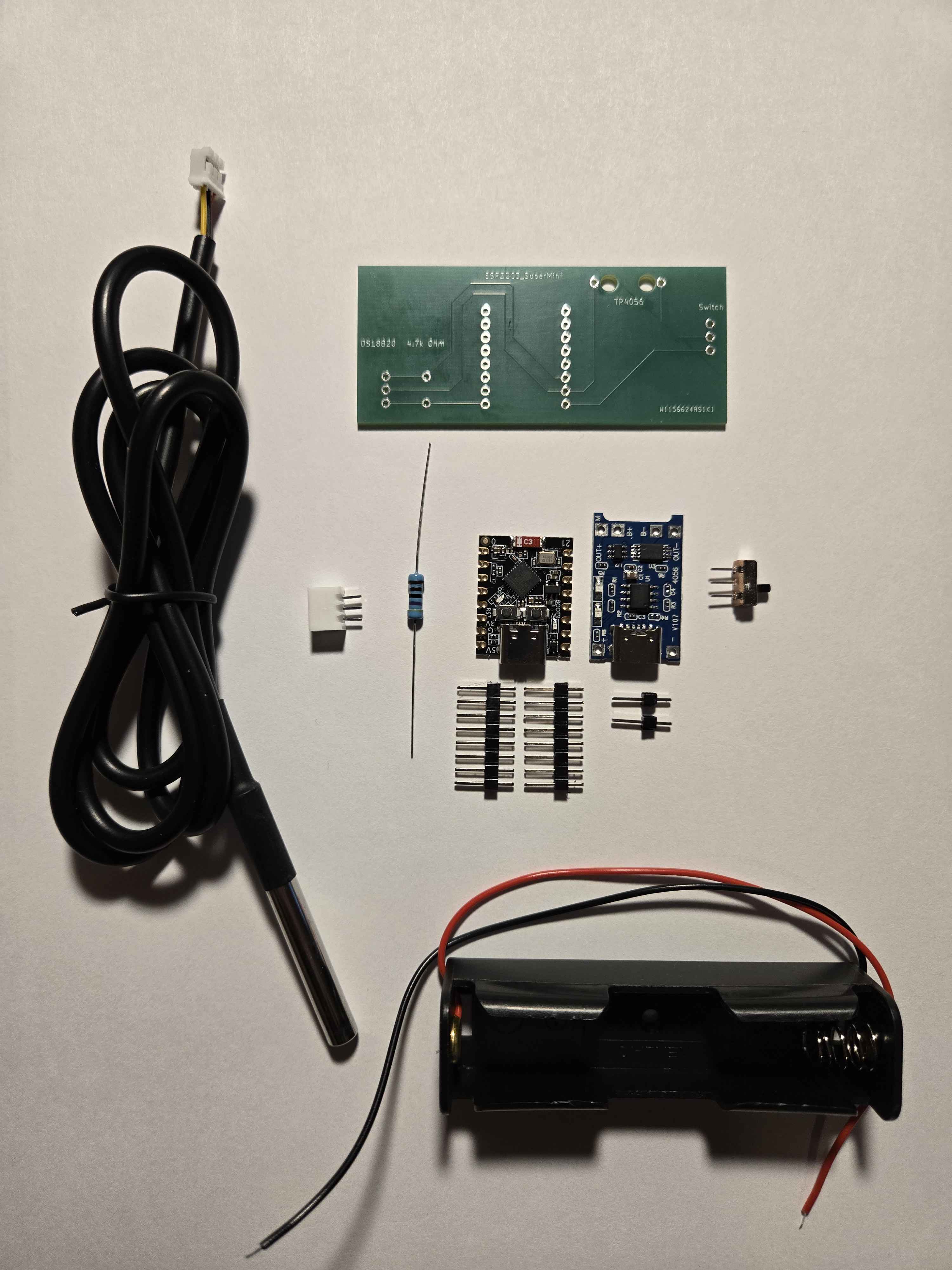
You supply: an 18650 cell. Protected or unprotected is fine here — the TP4056 module provides protection. (This is the one product where your unprotected cells are OK.)
Tools
Soldering iron + solder · flush cutters · USB-C data cable (not charge-only) · Chrome / Edge / Opera on desktop · multimeter (for the battery polarity check).
Step 1 — Solder the modules & parts
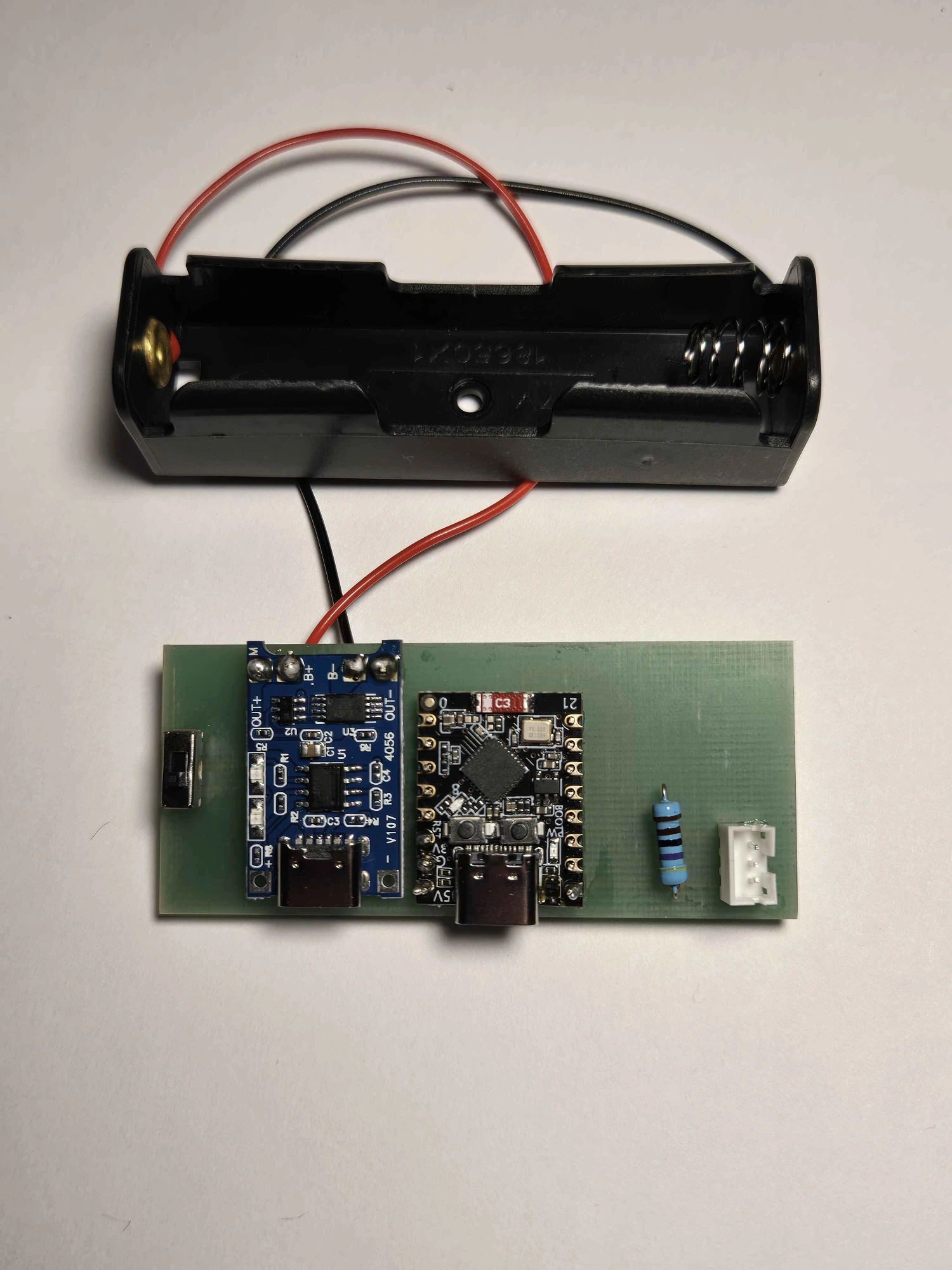
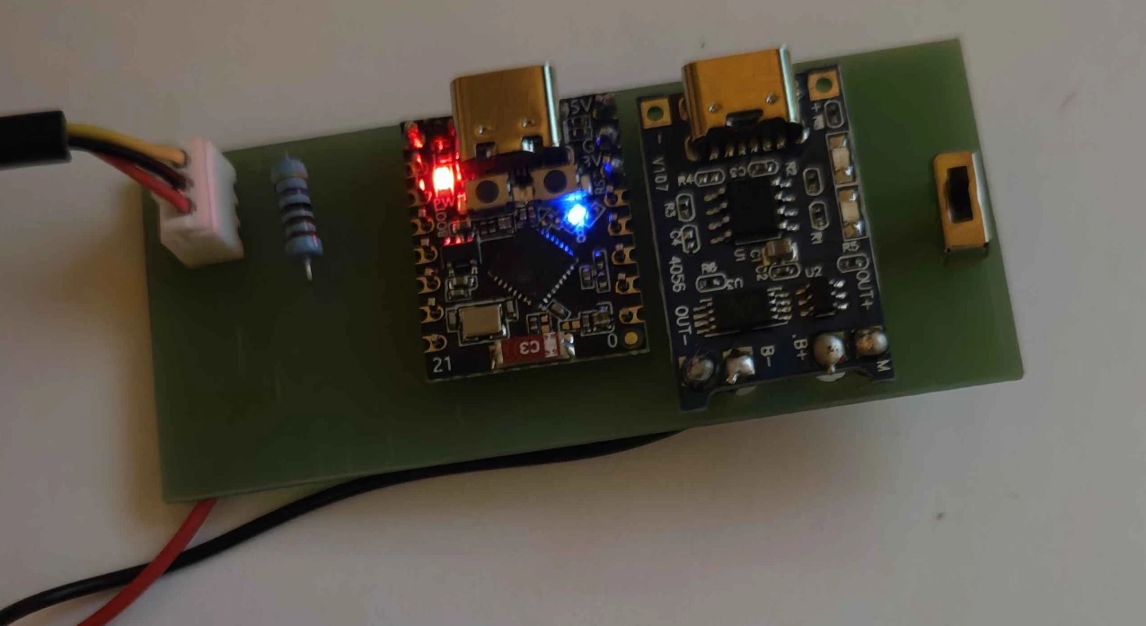
Solder header rows first, then seat each module onto them. Point both USB-C ports toward the board edge.
- ESP32-C3 SuperMini — solder its header rows to the carrier; USB-C facing out.
- TP4056 module — solder in place; its USB-C facing out.
- 4.7 kΩ resistor — in the DS18B20 pull-up position (marked on silk).
- SPDT slide switch — seat flat, solder the 3 pins.
Trim leads flush. Check for solder bridges on the header rows.
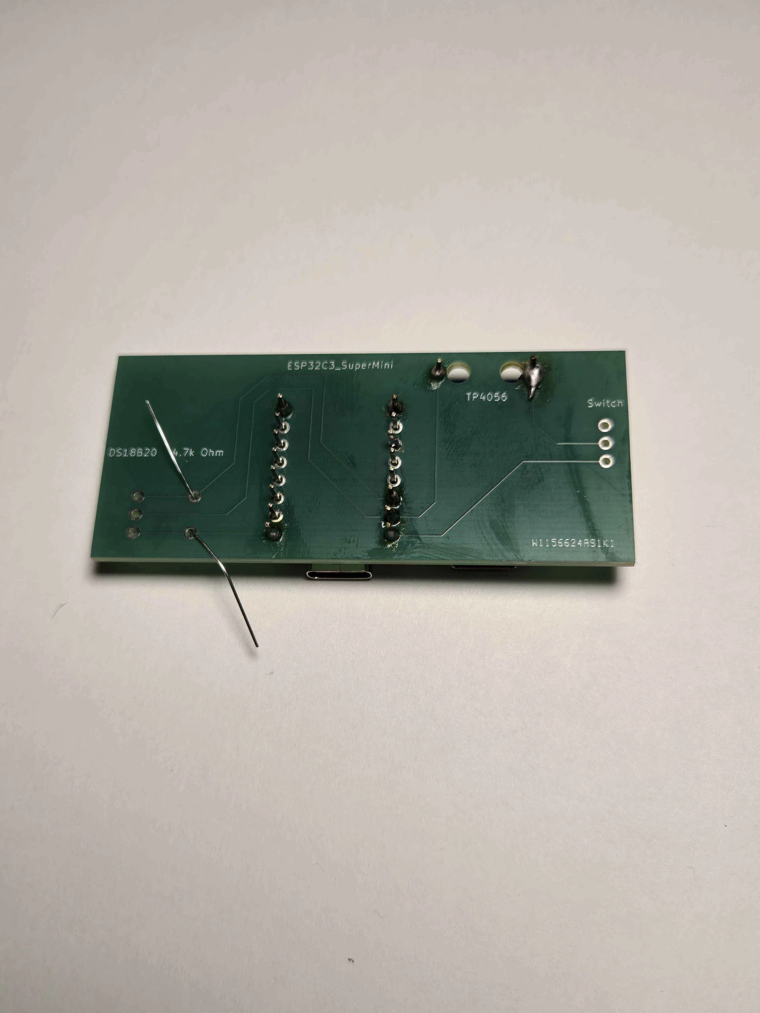
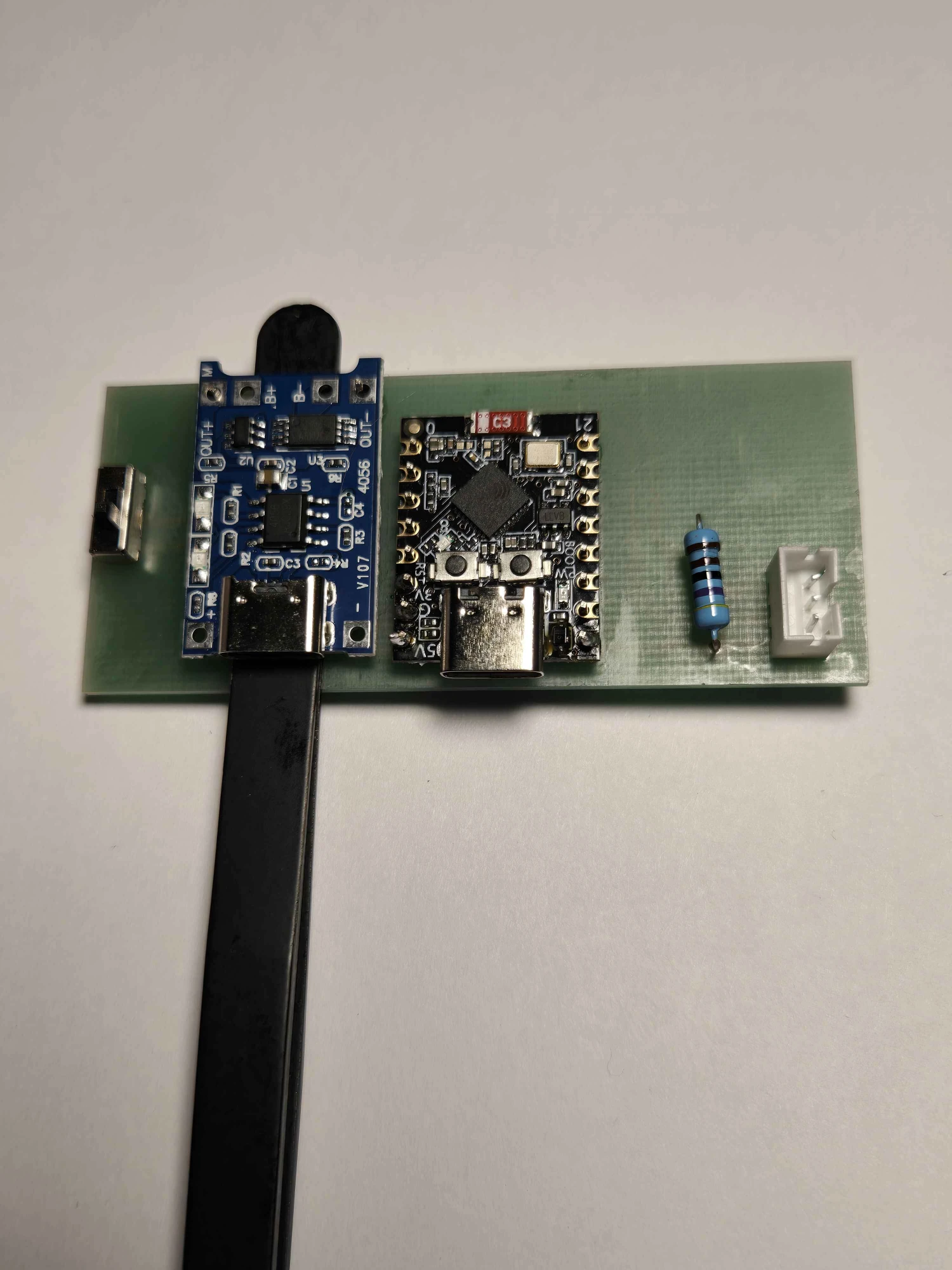
Two USB-C ports: the SuperMini's port is for flashing & data; the TP4056's is for charging only. Don't mix them up in Step 5.
Step 2 — Wire the probe
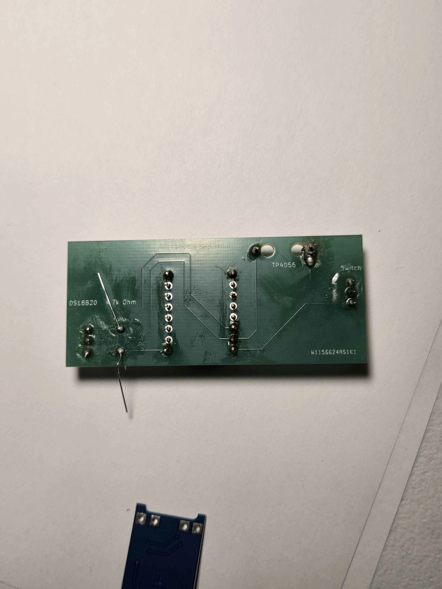
Connect the DS18B20's three wires at the DS18B20 pads: VCC / DATA / GND (follow the silk). The 4.7 kΩ pull-up you just soldered handles the DATA line.
Step 3 — Wire the battery ⚠️
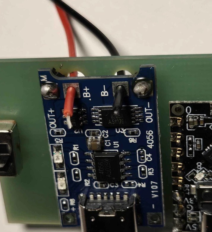
- Connect the 18650 holder to the carrier's battery pads (to the TP4056 module's B+ / B−).
- Confirm polarity with a multimeter — holder red (+) → B+, black (−) → B−. Reversed polarity can damage the module/board.
- Protected or unprotected cell both work (module has protection). Insert the cell with the switch OFF.
Step 4 — Power check
With the switch OFF, plug in the SuperMini USB-C: the onboard LED should light — USB powers the board directly, the switch only gates the battery. Then unplug USB and flip the switch ON: the LED should light again, now running from the cell. If anything gets warm either way, unplug and re-check Step 1 for bridges.
Step 5 — Flash the firmware (browser)
- Open the Setpoint web flasher in Chrome/Edge/Opera.
- Plug the SuperMini's USB-C into your computer with the power switch OFF. USB powers the board on its own for flashing; keeping the switch off stops USB power from back-feeding the cell through the TP4056.
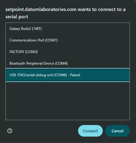
- Click Install/Connect, choose the port, flash. The C3 flashes natively over USB — no adapter.
✅ Firmware just works: the stock v2.9.4 image already targets this board — DS18B20 on GPIO5, status LED on the SuperMini's GPIO8 (auto-selected for the ESP32-C3 target). One image fits both the kit and the finished product; no special build needed.
Step 6 — Join Wi-Fi
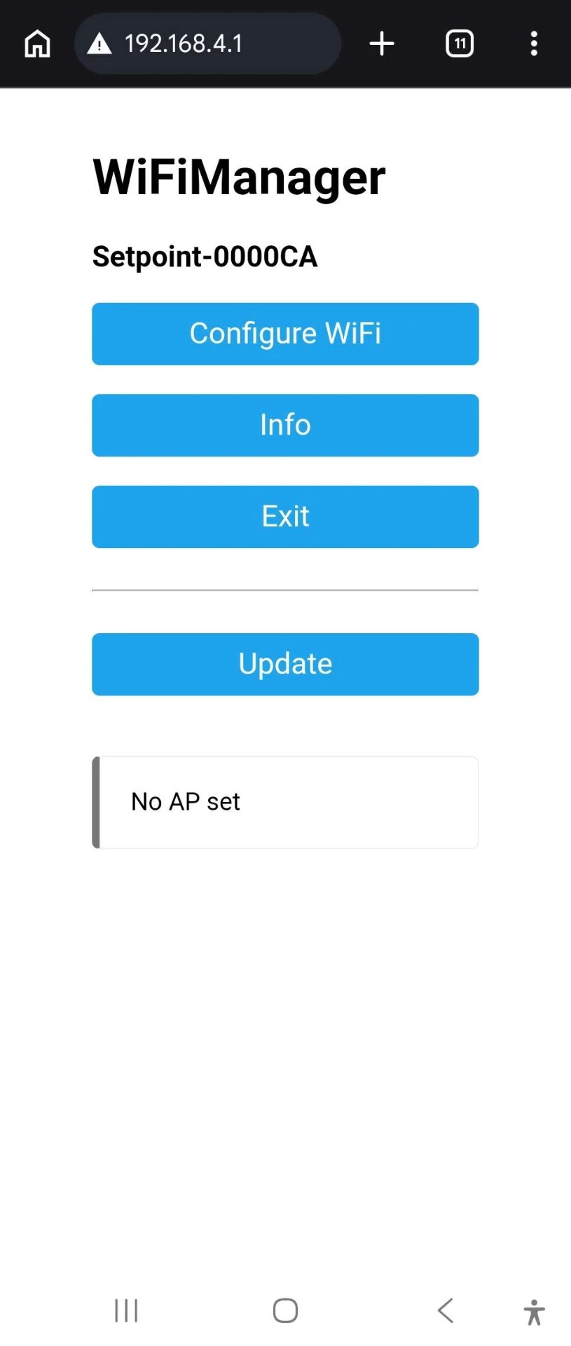
On first boot the board opens its setup portal. Connect to it, pick your 2.4 GHz network, save. It reconnects on its own afterward.
Step 7 — Verify
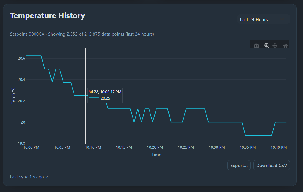
Open your Setpoint dashboard — the probe should appear and report temperature. Pinch the tip; the reading should rise. Set a threshold and confirm the alert fires.
🛡️ First launch — a security prompt is normal. The dashboard installer isn't code-signed yet, so on Windows you may see "Windows protected your PC" — click More info → Run anyway. On macOS you may see "can't be opened because Apple cannot check it" — right-click the app → Open → Open (once). This is expected and safe; it just means we haven't purchased a signing certificate yet. Full install steps →
✅ Done.
Safety
- The TP4056 module provides cell protection, but still verify battery polarity before first power-on.
- Don't leave the first charge unattended; confirm the cell doesn't get hot.
- Not a certified medical/food-safety/life-safety device. DIY builds carry no hardware warranty.
Troubleshooting
| Symptom | Fix |
|---|---|
| No LED on USB | Bridge · charge-only cable — use a data cable · wrong USB-C port (use the SuperMini's) |
| No LED on battery (USB works) | Power switch is OFF · cell flat or reversed — recheck B+/B− polarity |
| Warm/hot | Short — unplug, re-inspect header rows and battery polarity |
| Flasher can't see port | Chrome/Edge/Opera, over HTTPS, data cable (not charge-only) |
| Port drops / board keeps re-connecting | Force download mode: hold BOOT, tap RST, release BOOT, then flash. Common on a blank C3/S3. |
| No temperature | Probe VCC/DATA/GND order wrong · cold joint at the DS18B20 pads (DATA = GPIO5) |
| Won't join Wi-Fi | Must be 2.4 GHz · re-enter password |
| No charge | Use the TP4056 USB-C port for charging (not the SuperMini's) |